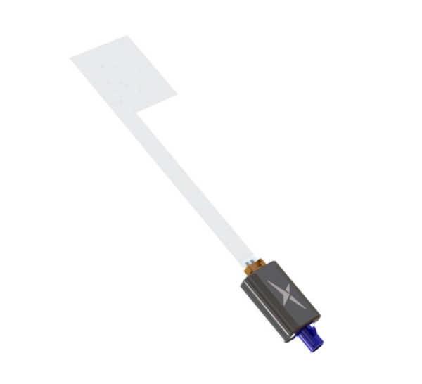
The TFX125.A
Flexible antennas have long been a staple in countless applications, offering adaptability across a wide array of uses. However, the « TFX125.A » flexible antenna stands out as truly unique. Its most remarkable feature? Near invisibility. This exceptional property caught our eye, especially considering its ability to seamlessly integrate into applications requiring internal antennas within metallic structures having for a transparent surface, such as a car’s window or within a digital signage display, the « TFX125.A » can be discreetly installed, sidestepping attenuation issues common with metallic structures while not being a visual obstruction.
More information regarding this antenna can be found on Taoglas website https://www.taoglas.com/product/multi-band-gnss-taoglas-invisible-antenna/
The purpose of this article is to get a ballpark idea on performance of this antenna by comparison to a standard L1/L2 active patch antenna.
Test setup
For this test, I will be using a couple of C099-F9P evaluation board from U-blox
https://www.u-blox.com/en/product/c099-f9p-application-board
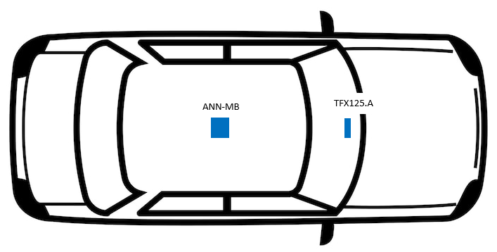
The C099 used as a reference is connected to the antenna ANN-MB, also from U-blox
https://www.u-blox.com/en/product/ann-mb-series
The second C099 is connected to the DUT using a 10 cm FAKRA to SMA cable.

Both boards are connected to a laptop, data are gathered and recorded using u-center evaluation software from u-blox.
https://www.u-blox.com/en/product/u-center
Measurement
Static test

For this test, the DUT and the REF antenna are placed on a structure of 2m height away by 4m from a wall of 5m height. The Idea is that this antenna can be used for example in signage application that can be installed on a sidewalk close to buildings.
First things first, a quick measurement of the TTFF from cold start
| REF | DUT |
| 20.402 | 34.743 |
An observation of 8 hours gave
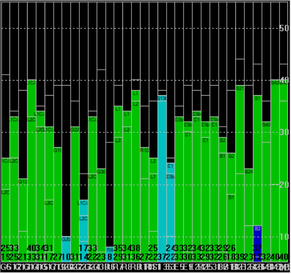
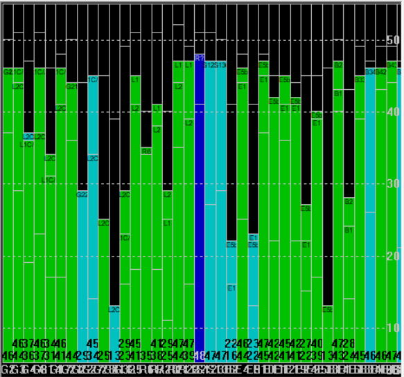
| Avr Nb Used SV | Avr SV C/N0 (dBHz) | Avr 3D Accuracy (m) | |
| REF | 28 | 26.22 | 3.656 |
| DUT | 25 | 33.24 | 1.473 |
The deviation map is an useful tool in this static setup
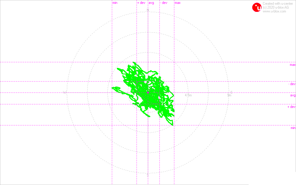
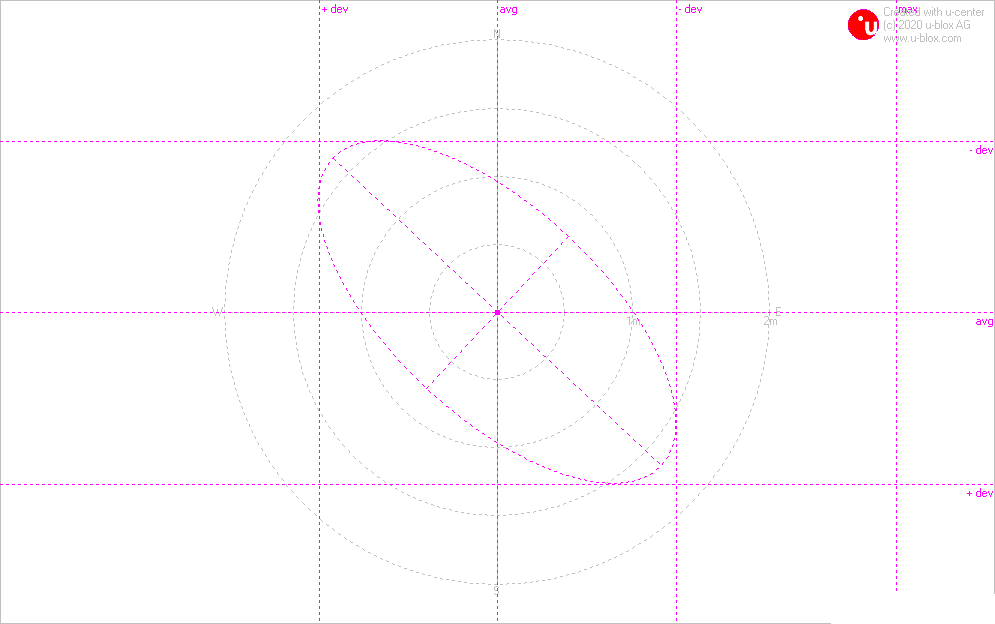
The deviation map shows a maximum deviation of around 4.5m and a mean deviation around 1.5m
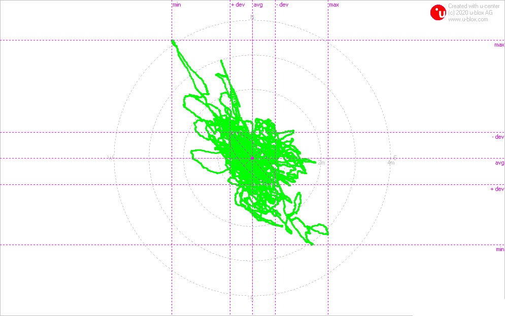
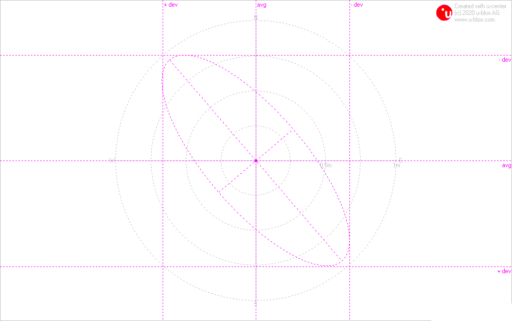
The REF receiver on the other hand shows a max deviation of 4m also and a mean deviation little less than 1m
| REF | DUT | |
| Max Dev | ~4m | ~4.5m |
| Mean Dev | ~0.8m | ~1.2m |
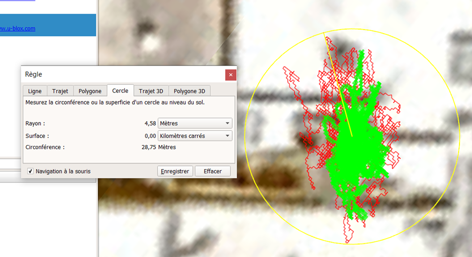
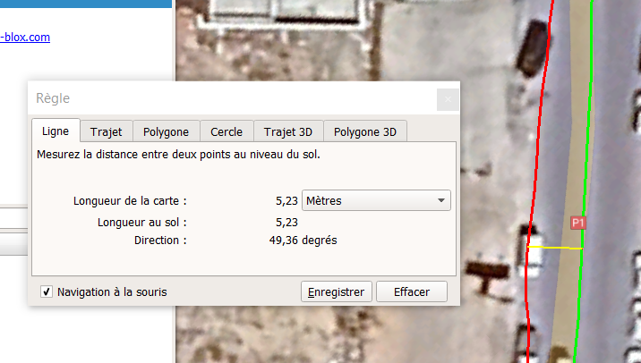
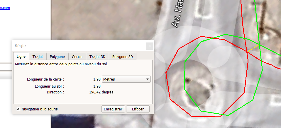
Projection of the tracking sessions from u-center to Google Earth confirm this measurement, Red line being the DUT and the Green one the Reference receiver.
Tracking Test
In this short test, the TFX125.A is fixed on a car windshield, worth to mention that the antenna is self-adhesive as it’s the case with most flexible antennas. The ANN-MB antenna will be installed on the roof of the car.

The TFX125.A performed nicely, it followed the road as good as the patch antenna, the gap between the two tracking is unnoticeable in this screenshot. It start from around 5m shortly after a cold start and vary between 1 to 3m on the rest of the test track.
Additional notes
Care should be taken when installing this antenna. Following the recommendation of the datasheet is crucial to not damage the antenna as it’s not design to resist to excessive pull force and can be damaged with loads of over 0.5 Kg.
Conclusion
Due to its design disparities, the TFX125.A isn’t expected to match the performance of the ANN-MB with it’s RHCP dual-feed patch antenna and an integrated high-gain LNA. Nonetheless, this demonstration has revealed that the TFX125.A unique’s nearly invisible antenna still delivers commendable results. Its capability makes it an ideal choice for applications where placement options are limited. Moreover, it seamlessly integrates into the visual aesthetics of the host system, whether it be a car window, windshield, or display, ensuring both functionality and elegance.
Disclaimer
- Test results shown in this article are only indicative, tests were performed in uncontrolled environment, repeatability is not guaranteed.
- This test purpose is to get a rough estimate on the performance of this antenna. Properly integrated antennas following the manufacturer recommendations are expected to show better performance.